

VHDL By Example – Fundamentals of Digital Design

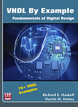
Assumes no previous digital design knowledge. Covers basic gates, logic equations, Boolean algebra, Karnaugh maps. Over 70 VHDL examples including a complete microprocessor core. Uses Aldec Active-HDL simulator. Can be used with any FPGA board. Includes 112 free YouTube video clips.
Preface
A major revolution in digital design has taken place over the past decade and more. Field programmable gate arrays (FPGAs) can now contain over a million equivalent logic gates and tens of thousands of flip-flops. This means that it is not possible to use traditional methods of logic design involving the drawing of logic diagrams when the digital circuit may contain thousands of gates. The reality is that today digital systems are designed by writing software in the form of hardware description languages (HDLs). The most common HDLs used today are VHDL and Verilog. Both are in widespread use. When using these hardware description languages the designer typically describes the behavior of the logic circuit rather than writing traditional Boolean logic equations. Computer-aided design tools are used to both simulate the Verilog or VHDL design and to synthesize the design to actual hardware.
This book assumes no previous knowledge of digital design. You start at the beginning, learning about basic gates, logic equations, Boolean algebra, and Karnaugh maps. In over 70 VHDL examples, you learn how to design combinational and sequential digital circuits, and even a complete microprocessor core, simulating them using the Aldec Active-HDL simulator. A free student edition of the Aldec Active-HDL simulator is available from Aldec, Inc. (www.aldec.com).
Once you simulate your digital design, you may want to download it to one of the many low-cost FPGA boards that are available on the market. This book could be used with any type of FPGA board. You would simply embed the examples we present in this book in a top-level design in which the inputs and outputs are tailored to your particular hardware. We will show some examples in this book on how to do this for a particular FPGA board made by Digilent, Inc., which contains a Xilinx FPGA, but you can easily adapt these examples to your particular FPGA board.
A new pedagogical method called “flipping” has been shown to be very effective in enhancing the classroom experience. Instead of coming to class unprepared and listening to an hour lecture and then going home to do homework, the order is “flipped” and you first watch short video clips online about a particular topic, and then the class time can be used to do “homework” problems, discussion, and answering questions. We have prepared 112 short video clips that cover all of the material in this book and they are available free on YouTube. To find these, go to www.youtube.com/user/LBEbooks/playlists and click on Digital Design VHDL. If you view these videos before going to class or reading the chapter, it will help you a lot!
Many colleagues and students have influenced the development of this book. Their stimulating discussions, probing questions, and critical comments are greatly appreciated.
Richard E. Haskell
Darrin M. Hanna
Table of Contents
1. Introduction to Digital Logic
1.1 Background
1.2 Digital Logic
1.3 VHDL
2. Basic Logic Gates
2.1 Truth Tables and Logic Equations
The Three Basic Gates
Four New Gates
2.2 Positive and Negative Logic: De Morgan’s Theorem
2.3 Sum of Products Design
2.4 Product of Sums Design
VHDL Examples
Example 1 – 2-Input Gates
Example 2 – Multiple Input Gates
Problems
3. Boolean Algebra and Logic Equations
3.1 Boolean Theorems
One-Variable Theorems
Two- and Three-Variable Theorems
3.2 Karnaugh Maps
Two-Variable K-Maps
Three-Variable K-Maps
Four-Variable K-Maps
3.3 Computer Mimimization Techniques
Tabular Representations
Prime Implicants
Essential Prime Implicants
VHDL Examples
Example 3 – Majority Circuit
Example 4 – 2-Bit Comparator
Problems
4. Implementing Digital Circuits
4.1 Implementing Gates
4.2 Transistor-Transistor Logic (TTL)
4.3 Programmable Logic Devices (PLDs and CPLDs)
A 2-Input, 1-Output PLD
The GAL 16V8
CPLDs
4.4 Field Programmable Gate Arrays (FPGAs)
VHDL Examples
Example 5 – Map Report
Problems
5. Combinational Logic
5.1 Multiplexers
2-to-1 Multiplexer
4-to-1 Multiplexer
Quad 2-to-1 Multiplexer
VHDL Examples
Example 6 – 2-to-1 Multiplexer: if Statement
Example 7 – 4-to-1 Multiplexer: Module Instantiation
Example 8 – 4-to-1 Multiplexer: case Statement
Example 9 – A Quad 2-to-1 Multiplexer
Example 10 – Generic Multiplexer: Parameters
Example 11 – Glitches
5.2 7-Segment Displays
VHDL Examples
Example 12 – 7-Segment Decoder: Logic Equations
Example 13 – 7-Segment Decoder: case Statement
5.3 Code Converters
Binary-to-BCD Converters
Shift and Add 3 Algorithm
Gray Code Converters
VHDL Examples
Example 14 – 4-Bit Binary-to-BCD Converter: Logic Equations
Example 15 – 8-Bit Binary-to-BCD Converter: for Loops
Example 16 – 4-Bit Binary to Gray Code Converter
Example 17 – 4-Bit Gray Code to Binary Converter
5.4 Comparators
Cascading Comparators
TTL Comparators
VHDL Examples
Example 18 – 4-Bit Comparator Using a VHDL Task
Example 19 – N-Bit Comparator Using Relational Operators
5.5 Decoders and Encoders
Decoders
TTL Decoders
Encoders
Priority Encoders
TTL Encoders
VHDL Examples
Example 20 – 3-to-8 Decoder: Logic Equations
Example 21 – 3-to-8 Decoder: for Loops
Example 22 – 8-to-3 Encoder: Logic Equations
Example 23 – 8-to-3 Encoder: for Loops
Example 24 – 8-to-3 Priority Encoder
Problems
6. Arithmetic Circuits
6.1 Adders
Half Adder
Full Adder
Carry and Overflow
TTL Adder
VHDL Examples
Example 25 – 4-Bit Adder: Logic Equations
Example 26 – 4-Bit Adder: Behavioral Statements
Example 27 – N-Bit Adder: Behavioral Statements
6.2 Subtractors
Half Subtractor
Full Subtractor
An Adder/Subtractor Circuit
VHDL Examples
Example 28 – 4-Bit Adder/Subtractor: Logic Equations
Example 29 – N-Bit Subtractor: Behavioral Statements
6.3 Shifters
VHDL Examples
Example 30 – 4-Bit Shifter
6.4 Multiplication
Binary Multiplication
Signed Multiplication
VHDL Examples
Example 31 – Multiplying by a Constant
Example 32 – A 4-bit Multiplier
Multiplication Operator
6.5 Division
Binary Division
VHDL Examples
Example 33 – An 8-bit Divider using a Task
6.6 Arithmetic Logic Unit (ALU)
VHDL Examples
Example 34 – 4-Bit ALU
Problems
7. Sequential Logic
7.1 Latches and Flip-Flops
SR Latch
Clocked SR Latch
D Latch
Edge-Triggered D Flip-Flop
VHDL Examples
Example 35 – Edge-Triggered D Flip-Flop
Example 36 – Edge-Triggered D Flip-Flop with Set and Clear
Example 37 – D Flip-Flops in VHDL
Example 38 – D Flip-Flop with Asynchronous Set and Clear
Example 39 – Divide-by-2 Counter
7.2 Registers
VHDL Examples
Example 40 – 1-Bit Register
Example 41– 4-Bit Register
Example 42 – N-Bit Register
7.3 Shift Registers
4-Bit Ring Counter
VHDL Examples
Example 43 – Shift Registers
Example 44 – Ring Counter
Example 45 – Debounce Pushbuttons
Example 46 – Clock Pulse
7.4 Counters
Arbitrary Waveform
VHDL Examples
Example 47 – 3-Bit Counter
Example 48 – Modulo-5 Counter
Example 49 – N-Bit Counter
Example 50 – Clock Divider: Modulo-10K Counter
Example 51 – Arbitrary Waveform
7.5 Pulse-Width Modulation (PWM)
Controlling the Speed of a DC Motor using PWM
Controlling the Position of a Servo using PWM
VHDL Examples
Example 52 – Pulse-Width Modulation (PWM)
Example 53 – PWM Signal for Controlling Servos
7.6 BASYS/Nexys-2 Board Examples
VHDL Examples
Example 54 – Shifting Data into a Shift Register
Example 55 – Fibonacci Sequence
Problems
8. State Machines
8.1 Mealy and Moore State Machines
8.2 A Moore Machine Sequence Detector
8.3 Mealy Machine Sequence Detector
VHDL Examples
Example 56 – Sequence Detector
Example 57 – Door Lock Code
VHDL Packages
Example 58 – Traffic Lights
Problems
9. Datapath and Control Unit
9.1 VHDL while Statement
Example 59 – GCD Algorithm – Part 1
9.2 Datapaths and Control Units
Example 60 – GCD Algorithm – Part 2
Example 61 – An Integer Square Root Algorithm
10. Integrating the Datapath and Control Unit
Example 62 – GCD Algorithm – Part 3
Example 63 – Integer Square Root – Part 2
11. Forth Core for FPGAs
11.1 The Forth Programming Language
11.2 Writing Programs in Forth
11.3 Forth Engines
Example 64 – FC16 Forth Core
Example 61 – An Integer Square Root Algorithm
Example 65 – A VHDL ROM
Example 66 – Distributed RAM/ROM
Example 67 – A Stack
Example 68 – Data Stack
Example 69 – Function Unit
Example 70 – Return Stack
Example 71 – FC16 Controller
Example 72 – GCD Forth Program
Example 73 – Square Root Forth Program
Appendix A – Aldec Active-HDL Tutorial
Part 1: Project Setup
Part 2: Design Entry
Part 3: Simulation
Part 4: Creating a Top-level Design
Appendix B – Number Systems
B.1 Counting in Binary and Hexadecimal
B.2 Positional Notation
B.3 Fractional Numbers
B.4 Number System Conversions
B.5 Negative Numbers
Appendix D – Installing Aldec Active-HDL
Appendix E – VHDL Quick Reference Guide
Index
(396 pages)