

Introduction to Digital Design Using Digilent FPGA Boards – Block Diagram/VHDL Examples

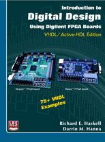
Contains 30 basic digital design examples for Digilent BASYS2 and NEXYS2 boards. Uses Active-HDL block diagram editor which automatically generates VHDL code. Good for beginners who want to understand digital design without learning VHDL first.
Preface
A major revolution in digital design has taken place over the past decade. Field programmable gate arrays (FPGAs) can now contain over a million equivalent logic gates and tens of thousands of flip-flops. This means that it is not possible to use traditional methods of logic design involving the drawing of logic diagrams when the digital circuit may contain thousands of gates. The reality is that today digital systems are designed by writing software in the form of hardware description languages (HDLs). The most common HDLs used today are Verilog and VHDL. Both are in widespread use. When using these hardware description languages the designer typically describes the behavior of the logic circuit rather than writing traditional Boolean logic equations. Computer-aided design tools are used to both simulate the VHDL or Verilog design and to synthesize the design to actual hardware.
This book assumes no previous knowledge of digital design. We use 30 examples to show you how to get started designing digital circuits that you can implement on a Xilinx Spartan3E FPGA using either the Digilent BASYS™ system board that can be purchased from www.digilentinc.com for $59 or the Digilent Nexys-2 board that costs $99. We will use Active-HDL from Aldec to design, simulate, synthesize, and implement our digital designs. A free student edition of Active-HDL is available from Aldec, Inc. (www.aldec.com). To synthesize your designs to a Spartan3E FPGA you will need to download the free ISE WebPACK from Xilinx, Inc. (www.xilinx.com). The Xilinx synthesis tools are called from within the Aldec Active-HDL integrated GUI. We will use the ExPort utility to download your synthesized design to the Spartan3E FPGA. ExPort is part of the Adept software suite that you can download free from Digilent, Inc. (www.digilentinc.com). A more complete book called Digital Design Using Digilent FPGA Boards – VHDL / Active-HDL Edition is also available from Digilent or LBE Books (www.lbebooks.com). This more comprehensive book contains over 75 examples including examples of using the VGA and PS/2 ports. Similar books that use Verilog are also available from Digilent or LBE Books.
Many colleagues and students have influenced the development of this book. Their stimulating discussions, probing questions, and critical comments are greatly appreciated.
Richard E. Haskell
Darrin M. Hanna
Table of Contents
Introduction – Digital Design Using FPGAs
Example 1 – Switch and LEDs
Example 2 – 2-Input Gates
Example 3 – Multiple-Input Gates
Example 4 – Equality Detector
Example 5 – 2-to-1 Multiplexer
Example 6 – Quad 2-to-1 Multiplexer
Example 7 – 4-to-1 Multiplexer
Example 8 – Clocks and Counters
Example 9 – 7-Segment Decoder
Example 10 – 7-Segment Displays: x7seg and x7segb
Example 11 – 2’s Complement 4-Bit Saturator
Example 12 – Full Adder
Example 13 – 4-Bit Adder
Example 14 – N-Bit Adder
Example 15 – N-Bit Comparator
Example 16 – Edge-Triggered D Flip-Flop
Example 17 – D Flip-Flops in VHDL
Example 18 – Divide-by-2 Counter
Example 19 – Registers
Example 20 – N-Bit Register in VHDL
Example 21 – Shift Registers
Example 22 – Ring Counters
Example 23 – Johnson Counters
Example 24 – Debounce Pushbuttons
Example 25 – Clock Pulse
Example 26 – Arbitrary Waveform
Example 27 – Pulse-Width Modulation (PWM)
Example 28 – Controlling Position of a Servo
Example 29 – Scrolling the 7-Segment Display
Example 30 – Fibonacci Sequence
Appendix A – Aldec Active-HDL Tutorial
Part 1: Project Setup
Part 2: Design Entry – sw2led.bde
Part 3: Synthesis and Implementation
Part 4: Program FPGA Board
Part 5: Design Entry – gates2.bde
Part 6: Simulation
Part 7: Design Entry – HDE
Part 8: Simulation – gates2
Appendix B – Number Systems
B.1 Counting in Binary and Hexadecimal
B.2 Positional Notation
B.3 Fractional Numbers
B.4 Number System Conversions
B.5 Negative Numbers
Appendix C – Basic Logic Gates
C.1 Truth Tables and Logic Equations
C.2 Positive and Negative Logic: De Morgan’s Theorem
C.3 Sum of Products Design
C.4 roduct of Sums Design
Appendix D – Boolean Algebra and Logic Equations
D.1 Boolean Theorems
D.2 Karnaugh Maps
Appendix E – VHDL Quick Reference Guide