

Digital Design Using Digilent FPGA Boards – Verilog/Vivado Edition
4th Edition

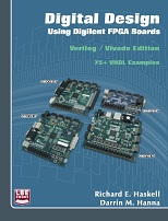
Most complete Verilog book with 13 chapters ranging from basic gates to VGA controller and PS2 protocol. Over 75 complete examples work on Digilent BASYS and NEXYS FPGA boards (Nexys2, Nexys3, Nexys4, Nexys4-DDR). Uses Xilinx Vivado WebPACK.
More in Verilog / FPGA
Preface
A major revolution in digital design has taken place over the past two decades. Field programmable gate arrays (FPGAs) can now contain over a million equivalent logic gates and tens of thousands of flip-flops. This means that it is not possible to use traditional methods of logic design involving the drawing of logic diagrams when the digital circuit may contain thousands of gates. The reality is that today digital systems are designed by writing software in the form of hardware description languages (HDLs). The most common HDLs used today are VHDL and Verilog. Both are in widespread use. When using these hardware description languages the designer typically describes the behavior of the logic circuit rather than writing traditional Boolean logic equations. Computer-aided design tools are used to both simulate the Verilog or VHDL design and to synthesize the design to actual hardware.
This book assumes no previous knowledge of digital design. You start at the beginning learning about basic gates, logic equations, Boolean algebra, and Karnaugh maps. In over 75 examples we show you how to design digital circuits using Verilog, simulate them, and synthesize the designs to a Xilinx FPGA on one of the following Digilent FPGA boards available from www.digilentinc.com: the Basys™2 Spartan- 3E FPGA board, the Nexys™2 Spartan-3E FPGA board, the Nexys™3 Spartan-6 FPGA board, the Nexys™4 Artix-7 FPGA board, or the Basys3™ Artix-7 FPGA board. The differences between these boards are summarized in Appendix C. To simulate and synthesize your designs to a Xilinx FPGA, you will need to download the free Vivado HL WebPACK from Xilinx, Inc. (www.xilinx.com). A tutorial on using Vivado is given in Appendix A. Each of the FPGA boards will need its unique user constraints file (.ucf), which identifies specific pin numbers for a particular board (see Appendix C). You can download these .ucf files from http://www.lbebooks.com/downloads.htm.
The simulation examples given in this book used the Aldec Active-HDL simulator. A free student edition of the Aldec Active-HDL simulator is available from Aldec, Inc. (www.aldec.com). If you would like to use that simulator to simulate your designs, a tutorial is available on http://www.lbebooks.com.
Many colleagues and students have influenced the development of this book. Their stimulating discussions, probing questions, and critical comments are greatly appreciated.
You can download the source code for all 76 Verilog examples in this book by going to URL listed in the book. There are also instructional tips and resources available for instructors who adopt the book.
Richard E. Haskell
Darrin M. Hanna
Table of Contents
1. Introduction to Digital Logic
1.1 Background
1.2 Digital Logic
1.3 Verilog
2. Basic Logic Gates
2.1 Truth Tables and Logic Equations
The Three Basic Gates
Four New Gates
2.2 Positive and Negative Logic: De Morgan’s Theorem
2.3 Sum of Products Design
2.4 Product of Sums Design
Verilog Examples
Example 1 – 2-Input Gates
Example 2 – Multiple Input Gates
Problems
3. Boolean Algebra and Logic Equations
3.1 Boolean Theorems
One-Variable Theorems
Two- and Three-Variable Theorems
3.2 Karnaugh Maps
Two-Variable K-Maps
Three-Variable K-Maps
Four-Variable K-Maps
3.3 Computer Mimimization Techniques
Tabular Representations
Prime Implicants
Essential Prime Implicants
Verilog Examples
Example 3 – Majority Circuit
Example 4 – 2-Bit Comparator
Problems
4. Implementing Digital Circuits
4.1 Implementing Gates
4.2 Transistor-Transistor Logic (TTL)
4.3 Programmable Logic Devices (PLDs and CPLDs)
A 2-Input, 1-Output PLD
The GAL 16V8
CPLDs
4.4 Field Programmable Gate Arrays (FPGAs)
Verilog Examples
Example 5 – Map Report
Problems
5. Combinational Logic
5.1 Multiplexers
2-to-1 Multiplexer
4-to-1 Multiplexer
Quad 2-to-1 Multiplexer
Verilog Examples
Example 6 – 2-to-1 Multiplexer: if Statement
Example 7 – 4-to-1 Multiplexer: Module Instantiation
Example 8 – 4-to-1 Multiplexer: case Statement
Example 9 – A Quad 2-to-1 Multiplexer
Example 10 – Generic Multiplexer: Parameters
Example 11 – Glitches
5.2 7-Segment Displays
Verilog Examples
Example 12 – 7-Segment Decoder: Logic Equations
Example 13 – 7-Segment Decoder: case Statement
Example 14 – Multiplexing 7-Segment Displays
Example 15 – 7-Segment Displays: x7seg and x7segb
5.3 Comparators
Cascading Comparators
TTL Comparators
Verilog Examples
Example 16 – 4-Bit Comparator Using a Verilog Task
Example 17 – N-Bit Comparator Using Relational Operators
5.4 Decoders and Encoders
Decoders
TTL Decoders
Encoders
Priority Encoders
TTL Encoders
Verilog Examples
Example 18 – 3-to-8 Decoder: Logic Equations
Example 19 – 3-to-8 Decoder: for Loops
Example 20 – 8-to-3 Encoder: Logic Equations
Example 21 – 8-to-3 Encoder: for Loops
Example 22 – 8-to-3 Priority Encoder
5.5 Code Converters
Binary-to-BCD Converters
Shift and Add 3 Algorithm
Gray Code Converters
Verilog Examples
Example 23 – 4-Bit Binary-to-BCD Converter: Logic Equations
Example 24 – 8-Bit Binary-to-BCD Converter: for Loops
Example 25 – 4-Bit Binary to Gray Code Converter
Example 26 – 4-Bit Gray Code to Binary Converter
Problems
6. Arithmetic Circuits
6.1 Adders
Half Adder
Full Adder
Carry and Overflow
TTL Adder
Verilog Examples
Example 27 – 4-Bit Adder: Logic Equations
Example 28 – 4-Bit Adder: Behavioral Statements
Example 29 – N-Bit Adder: Behavioral Statements
6.2 Subtractors
Half Subtractor
Full Subtractor
An Adder/Subtractor Circuit
Verilog Examples
Example 30 – 4-Bit Adder/Subtractor: Logic Equations
Example 31 – N-Bit Subtractor: Behavioral Statements
6.3 Shifters
Verilog Examples
Example 32 – 4-Bit Shifter
6.4 Multiplication
Binary Multiplication
Signed Multiplication
Verilog Examples
Example 33 – Multiplying by a Constant
Example 34 – A 4-bit Multiplier
6.5 Division
Binary Division
Verilog Examples
Example 35 – An 8-bit Divider using a Task
6.6 Arithmetic Logic Unit (ALU)
Verilog Examples
Example 36 – 4-Bit ALU
Problems
7. Sequential Logic
7.1 Latches and Flip-Flops
SR Latch
Clocked SR Latch
D Latch
Edge-Triggered D Flip-Flop
Verilog Examples
Example 37 – Edge-Triggered D Flip-Flop
Example 38 – Edge-Triggered D Flip-Flop with Set and Clear
Example 39 – D Flip-Flops in Verilog
Example 40 – D Flip-Flop with Asynchronous Set and Clear
Example 41 – Divide-by-2 Counter
7.2 Registers
Verilog Examples
Example 42 – 1-Bit Register
Example 43– 4-Bit Register
Example 44 – N-Bit Register
7.3 Shift Registers
4-Bit Ring Counter
Verilog Examples
Example 45 – Shift Registers
Example 46 – Ring Counter
Example 47 – Debounce Pushbuttons
Example 48 – Clock Pulse
7.4 Counters
Arbitrary Waveform
Verilog Examples
Example 49 – 3-Bit Counter
Example 50 – Modulo-5 Counter
Example 51 – N-Bit Counter
Example 52 – Clock Divider: Modulo-10K Counter
Example 53 – Arbitrary Waveform
7.5 Pulse-Width Modulation (PWM)
Controlling the Speed of a DC Motor using PWM
Controlling the Position of a Servo using PWM
Verilog Examples
Example 54 – Pulse-Width Modulation (PWM)
Example 55 – PWM Signal for Controlling Servos
7.6 BASYS/Nexys-2 Board Examples
Verilog Examples
Example 56 – Loading Switch Data into a Register
Example 57 – Shifting Data into a Shift Register
Example 58 – Scrolling the 7-Segment Display
Example 59 – Fibonacci Sequence
Problems
8. State Machines
8.1 Mealy and Moore State Machines
8.2 A Moore Machine Sequence Detector
8.3 Mealy Machine Sequence Detector
Verilog Examples
Example 60 – Sequence Detector
Example 61 – Door Lock Code
Example 62 – Traffic Lights
Problems
9. Datapath and Control Unit
9.1 Verilog while Statement
Example 63 – GCD Algorithm – Part 1
9.2 Datapaths and Control Units
Example 64 – GCD Algorithm – Part 2
Example 65 – An Integer Square Root Algorithm
10. Integrating the Datapath and Control Unit
Example 66 – GCD Algorithm – Part 3
Example 67 – Integer Square Root – Part 2
11. Memory
Example 68 – A Verilog ROM
Example 69 – Distributed RAM/ROM
Example 70 – Block RAM/ROM
12. VGA Controller
Example 71 – VGA Stripes
Example 72 – VGA PROM
Example 73 – Sprites in Block ROM
Example 74 – Screen Saver
13. PS/2 Port
Example 75 – Keyboard
Example 76 – Mouse
Appendix A – Aldec Active-HDL Tutorial
Part 1: Project Setup
Part 2: Design Entry
Part 3: Simulation
Part 4: Creating a Top-level Design
Part 5: Synthesis and Implementation
Part 6: Program FPGA Board
Appendix B – Number Systems
B.1 Counting in Binary and Hexadecimal
B.2 Positional Notation
B.3 Fractional Numbers
B.4 Number System Conversions
B.5 Negative Numbers
Appendix C – Making a Turnkey System
Appendix D – Digilent FPGA Board Comparison Chart
Appendix E – Installing the Xilinx Vivado WebPACK
Appendix F – Verilog Quick Reference Guide
Index
(365 pages)
Resources
Whether you are teaching a workshop or course using this book or learning to design digital hardware on your own, we would like to point out that the following resources are available to accompany the book:
1. You can download the source code for all 76 Verilog examples in this book by going to the URL given in the book.
2. There are 112 short video modules available on YouTube™ that range from 3 – 15 minutes each, with an average length of approximately 7 minutes, to provide visual and audio instruction on the topics contained in this book. The examples are in VHDL, but can easily be adapted to Verilog. These serve as excellent tutorials or follow-up materials for students to review concepts taught in a lecture course.
You can search LBE Books on YouTube™ or go directly to our video playlist at:
http://www.youtube.com/playlist?list=PL7kkolCtIBKLukrBsEDwKRTE64JvaJDhM
Topic Order and Lecture Support for Instructors
This book was designed to be modular. It can be used to present digital design in the traditional format starting with combinational logic followed by sequential logic and design. Alternatively, it can be used to teach a digital design course using problem-based learning, described below. The following tips are from instructors who have had notable success using this book:
1. Assign one or more videos (a total of 15-25 minutes) for students to watch before coming to the lecture. These may be videos containing review material so that you do not have to spend time reviewing in class or videos that explain new topics that you are going to cover in class so that students come prepared. You may also wish to give a short pre-lecture quiz at the beginning of class or assign a short homework assignment that the student can easily complete while watching the videos to turn on the day of the lecture to ensure that students are prepared.
2. Instead of using the book in order which presents concepts in a traditional order, follow a problem-based approach in which students are taught to design components based on problem statements and circuits designed in class. This means that components are taught as-needed, therefore, combinational and sequential components are taught concurrently. This way, students can get to meaningful design earlier in the course.
An example of this that has been employed in a Junior-level course is starting with presenting the problem of creating a circuit to compute the GCD for two integers using Euclid’s GCD. The topics for lecture would follow the book order from the beginning including examples 1 through 10 for introductory concepts, Verilog syntax including port maps, and multiplexers. Following example 10 would be comparators including example 21, adders and subtractors including examples 27 through 31, and latches and registers including examples 37 through 44. This completes the knowledge and components to design a digital circuit for Euclid’s GCD. Then, other problems could be presented such as computing the integer square root, a mouse driver, a keyboard driver, a VGA controller, and more, eventually covering all topics in the course objectives.